Index Table - Dividing Head
Worm and Worm gear
Making a worm and a worm gear seems harder than it really is. Making a worm is no more than a tread on the lathe. Because module gears have a pressure angle of 20 degrees, the cutting tool to make a worm must have an angle of 40 degrees. The module of the worm gear determines the speed. For this index table I chose a worm gear module 1. The pitch of the worm is then similar to
module x pi = 1 x pi = 1 x 3.14
Some lathes have change gears to cut module tread. For them there
is no problem. If your lathe is not equipped to cut module tread you must
calculate the change gears. Because 3.14 is not usable for gear calculations
we use for pi the fraction 22/7. As you can see, you need a gear with a
multiple of 11. Usually you'll be ready if you buy a gear with 44 teeth.
If your lathe has a gearbox with 4 gears, the calculation can be made with the
following formula:
A/B x 22/7 x Longitudinal screw feed
If your lathe has a gearbox with 6 gears, the calculation can be made with the following formula:
M/N x A/B x 22/7 x Longitudinal screw feed
My lathe has 6-wheel gearbox and a longitudinal screw feed of 3mm. I have the following gears used
28/35 x 44/24 x 30/42 x 3 = 3.14
Click to enlarge pictures.
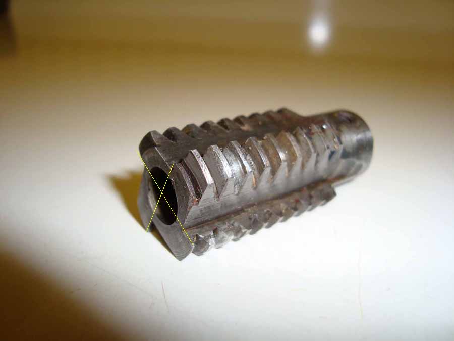
Make on your lathe two identical worms such as drawing 10. Take it from harden able steel, as tool steel, stubs steel, or C45 steel. In one worm are milled away four corners as the picture shown. The cut surfaces should be in the center of the worm, as indicated by the yellow lines. The depth should be at least 2.5 mm deep. Carefully remove any burrs and polish the cut surfaces with a sandstone. Then the cutter and the worm may be hardened. It is not necessary to harden the worm.
The worm wheel has 72 teeth and is made of bronze. Turn the contour of the worm wheel just right with a diameter of 75mm. The hollowing out comes round during milling. To make a worm gear you need a few accessories. It will be clear later. The teeth of the worm gear must be milled a little bit so the worm-milling tool has grip during the beginning of the milling. The cutter for this job is not important. It must not a module-milling tool. I have used a small T-slot cutter. You just need ensure that you mills not too deep. The angle should be approximately 3 degrees. This is also the angle of the teeth of the worm gear. To make the dividings I used an old dividing head of my previous EMCO lathe.
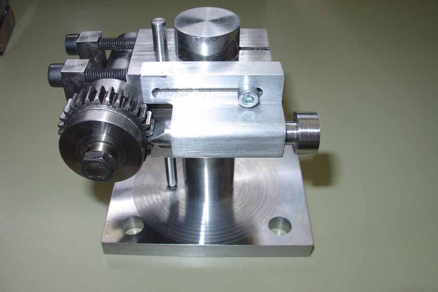
You can also create a simple dividing head. This allows you to make divisions simple using a gear.
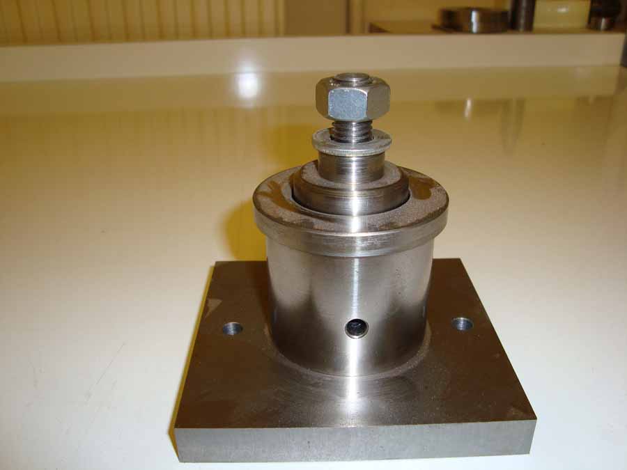
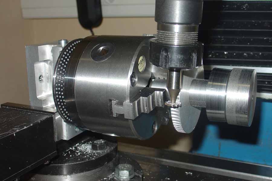
To cut the worm gear you need a support. This I mounted on the lathe in place of the tool post slide. The worm gear is mounted on this support with a nut. The support must be filled out so the center of the worm gear is just on the center height of the lathe.
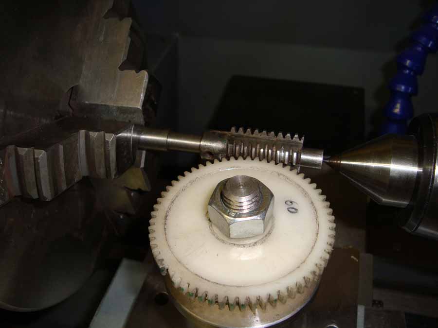
The picture beside shows the arrangement for the milling of the worm gear. The picture is made for demonstration only and not with the real worm gear. When this arrangement is finished the worm gear can be milled. Turn the cross slide forward until the cutter just touch the surface of the worm gear. This is the zero point. Set the vernier of the cross slide to zero. Now place the cutter in the pre milled teeth. Start the lathe at the lowest possible speed. The worm gear will now be rotated. Each time the worm has made a full revolution press the worm gear with the cross slide careful closer against the cutter. Repeat until you have a depth of 2.5 mm reached. For the last 0.25 mm to mill put the speed of the lathe a little bit higher (150 rpm) so the teeth will now be nice polished. The total tooth depth is 2.75 mm.